Generally, one has to enter a value for every parameter a given function uses.

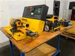
Sixth column always contains the parameter called H, which generally corresponds to the amount of material taken in a given step in one of the canned functions. The fifth column has the widest number of "interpretations," signifying the feed rate, F, the pitch of a thread (which, unfortunately, is also called K), the tool number, T, or the line number, L. Note that as one is looking down on the lathe, the positive Z axis points along the spindle axis, away from the spindle and the positive X axis points away from the machine. The third and fourth columns are used to store the X and Z values for a given move (actually X can also be the pause time), or the I and K distances to the center point (if one is using the M99 command). By default, the machine assumes you are entering a G-code; to get an M-Code, press the Minus "-" key. (Thus you really only need to worry about entering data in the remaining five columns.) The second column is for the G or M command. The first column contains the program number, and the computer essentially takes care of this for you.

Further, all the data you enter goes into one of six columns. Entering Data When you are keying data directly into the Emco Compact 5 CNC Lathe, you can really only input numbers. The significance of this shall be seen when discussing the G02/G03 commands. Although no Y or J parameters exist, the implied direction of the Y-axis is also shown. Notice that positive Z points away from the chuck, while positive X essentially points "away" from the machine. Additionally, Figure 3.1 demonstrates the direction of the X and Z-axes. how many inches or millimeters each unit represents) is shown in Table 3.2, along with the meaning of the various parameters. (As you will notice, there is no G-Code to do this.) The scaling (i.e.
#Emco compact 5 cnc simulator code#
(In other words the code is not entered in floating point format.) Also, the machine is set to either English or metric units by setting the switch to either inches or mm. Table 3.1: Emco Codes (continued) Command G95 M00 M03 M05 M06 M08 M09 M17 M22 M23 M26 M30 M98 M99 Commandįunction Feed in mm/rev (or in/rev) Programmed Stop (Pause) Spindle ON, CW Spindle OFF Tool Length Compensation Switch exit X62 PIN 15 HIGH Switch exit X62 PIN 15 LOW Return Command to the Main Program Switch exit X62 PIN 18 HIGH Switch exit X62 PIN 18 LOW Switch exit X62 PIN 20 End of Program (Must be in Program) Automatic Compensation of Play Circle Parameter Functionģ.4.2 G-Code Parameters Meaning and Ranges of Parameters Note that when programming on the Emco Compact 5 CNC Lathes, every parameter will have an integer value. 3.1 G and M codes on the Emco Compact 5 CNC Lathes 3.4.1 Summary of Commands Table 3.1: G and M-codes Available with the Emco Compact 5 CNC Lathes (Extension A6C 114 004) Command Function G00 Rapid Traverse G01 Linear Interpolation G02 CW Circular Interpolation (2-d) G03 CCW Circular Interpolation (2-d) G04 Dwell G21 Empty Line G24 Radius Programming G25 Sub-routine call-up G27 Jump Instruction G33 Threading with Constant Pitch G64 Feed Motors Currentless G65 Cassette Operation G66 RS 232 Operation G73 Chip Breakage Cycle G78 Threading Cycle G81 Drilling Cycle G82 Drilling Cycle with Dwell G83 Drilling Cycle, Deep Hole with Withdrawal G84 Longitudinal Turning G85 Reaming Cycle G86 Grooving with Division of Cut (parameter H) G88 Facing with Division of Cut G89 Reaming and Drilling with Dwell G90 Absolute Mode canceled only by G91 G91 Incremental Mode canceled only by G90 or G92 G92 Set Register (Zero Point Offset) Absolute Mode G94 Feed in mm/min (or in/min)


 0 kommentar(er)
